Design Automation through a Generative Engineering Approach: Development of a Reusable Wing Model
In this article, we'll explore how to build reusable generative engineering applications using open-source tools and a knowledge-based engineering (KBE) approach, through the example of a rectangular wing generator web application. Similar applications can automate early-stage design processes and enable the exploration of a wide range of design parameter combinations, avoiding repetitive manual work on adapting geometry and running repetitive simulations.
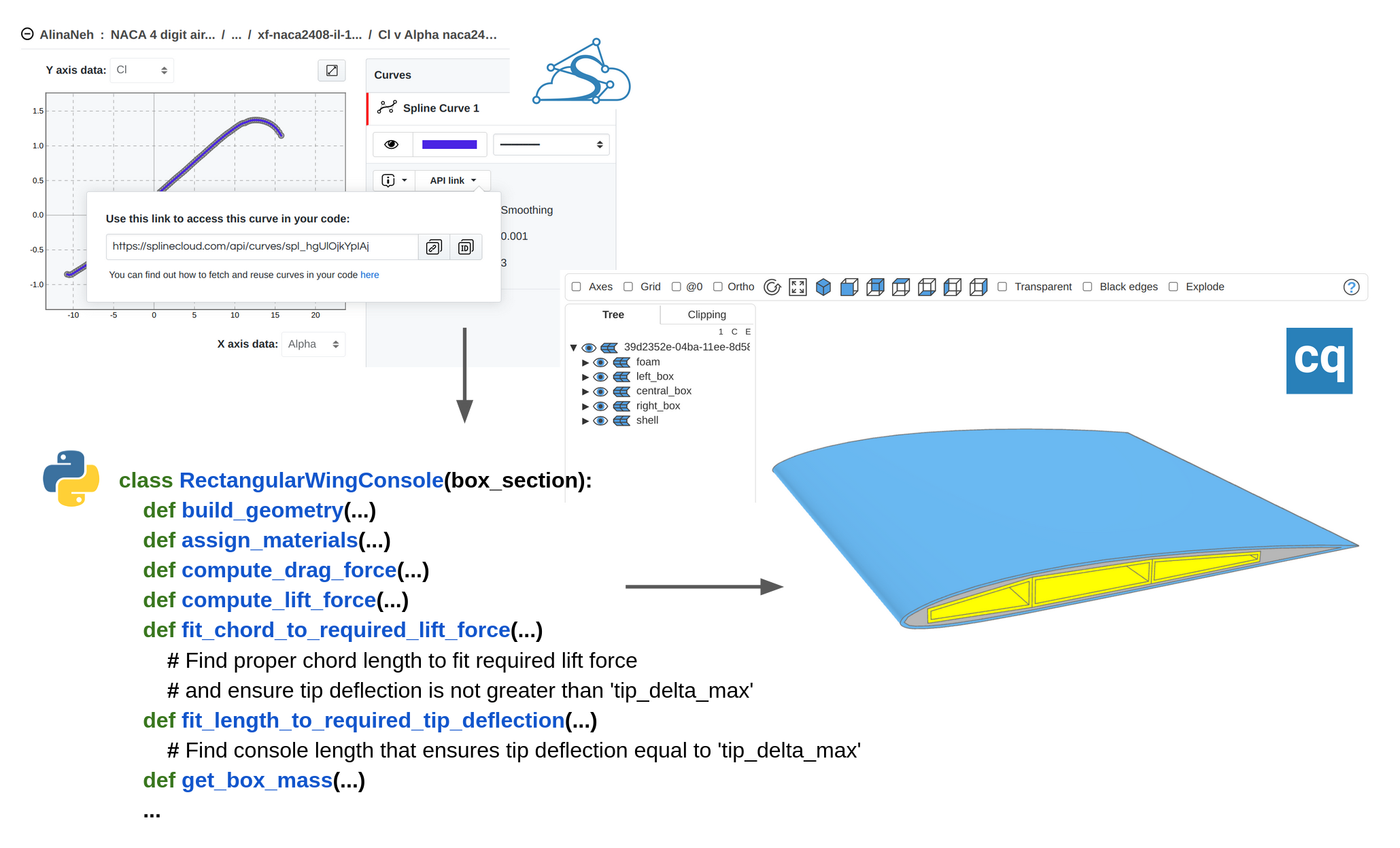
The important aspect of this approach is the efficient reuse of airfoil shape and performance data (aerodynamic coefficients), organized in SplineCloud repositories and accessible over SplineCloud API. Another important feature is the open-source architecture: the application is built entirely with Python, CadQuery, NumPy + SciPy, and Streamlit.
All engineering analyses in this example are automated using custom numerical algorithms that formalize domain knowledge, making it reusable for other projects. For simplicity, no finite element methods (FEM) are used, though future work may explore integrating FEM into the analysis pipelines. This case study demonstrates how combining domain knowledge, rule-based logic, and programmable CAD tools can drastically accelerate design space exploration — a critical factor for making high-quality, knowledge-informed decisions at the early stages of engineering design.
A Few Words About Generative Engineering and KBE
Traditional CAD workflows in aerospace often rely on continuous redesigns and adjustments, making the early design phases slow, repetitive, and vulnerable to errors. Changes to wing shape or structural parameters typically require reworking the entire model (or solving conflicts in model history), which is exhaustive and may delay work on detailed design and engineering analyses.
By contrast, generative engineering takes automation further by using algorithms to create whole families of designs based on variables, rules, and goals. In academic terminology, this approach is a part of the Knowledge-Based Engineering (KBE) methodology [1,2]. In general form, this methodology represents the approach towards design and engineering by integrating object-oriented programming, artificial intelligence (AI), and computer-aided design (CAD).
It embeds expert knowledge, design rules, and decision-making logic directly into engineering tools and processes. Instead of manually applying expertise every time a new design is created, KBE systems formalize this knowledge into reusable models, templates, and algorithms.

Typically, a KBE application consists of three key components:
- Knowledge Base: A structured repository where reusable domain knowledge, experimental or statistical data, and engineering heuristics are stored. This ensures that expert knowledge is systematically captured and easily accessible for automation.
- KBE Model: A mathematical and logical model that encapsulates design rules and methodologies to perform computations, generate geometry, and solve optimization problems.
- Graphical User Interface (GUI): An interactive layer that allows users to input design parameters, view generated geometries, monitor calculation results, and interact with the system intuitively without needing to dive into the code.
In the context of early-stage design, a generative wing console application, based on KBE principles, allows us to:
- Automatically generate many wing console variants based on a few high-level parameters and predefined rules. Integrate structural constraints like lift force and deflection limits directly into the design logic.
- Use lightweight numerical analysis instead of full-scale finite element models (FEM) for rapid evaluations.
- Simplify and speed up exploration of the design space to make informed decisions earlier in the design process.
In this article, you will learn how, by combining KBE methodologies with open-source tools you can unlock a faster, smarter way to automate the design process.
Wing Console Mathematical Model
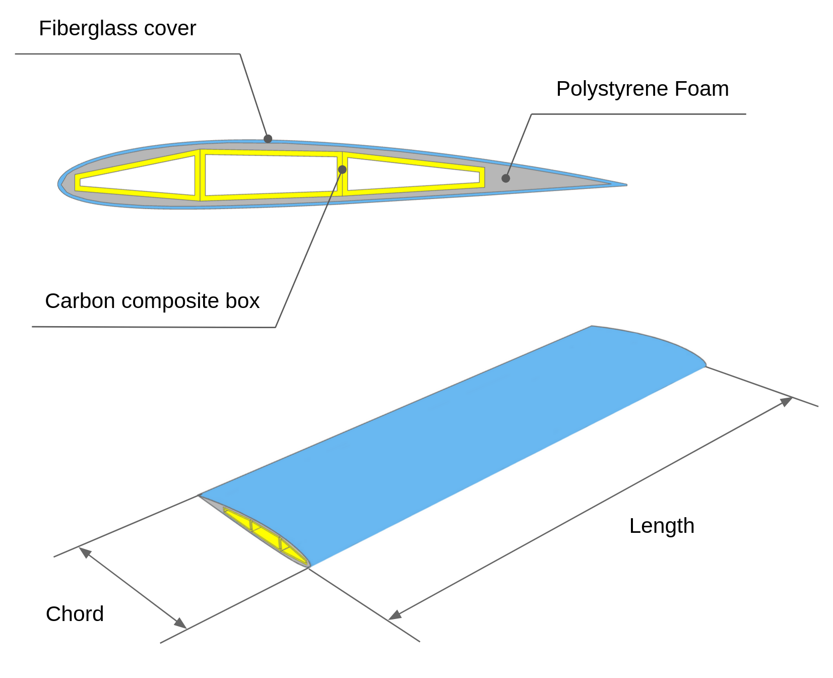
So let’s start with defining the model. A wing structure in this example is represented by three components:
- Internal thin-walled box assembly (aluminium, fiberglass, or carbon composite);
- Airfoil shaper - a lightweight intermediary body (polystyrene foam, LW-PLA, or other);
- Outer shell (fiberglass coat).
In this example, no other structural options will be analyzed. So, to some extent, we will study a parametric model, where only dimensions can change. However, adaptations of dimensions to the various airfoils are implemented in the algorithmic approach, which goes beyond the capabilities of traditional CAD systems.
Since we rely on a FEM-free approach, the next simplifications and assumptions are taken to enable a fast preliminary engineering analysis process:
- the internal box withholds all loads - the contribution of other components is neglected;
- no torque on a wing is analyzed for simplicity;
- materials are considered to have isotropic properties;
- no aeroelasticity effects are considered (wing load scheme is taken for the undeformed wing);
- a simplified (uniform) wing load scheme was considered.
KBE Model of The Wing Console
To create a generative model, we use CadQuery [3], a powerful Python library for building parametric 3D CAD models programmatically. The alternative approach would be to use an API to FreeCAD; however, the CadQuery is a cleaner approach, which does not require installation of a heavy-weight CAD system. And since we want to build a reusable application we can not rely on APIs to proprietary CAD systems. Thus, in our case the geometry of the wing console is defined entirely through code.
The generative model of the wing is based on the following principles:
- Object-oriented Approach: All design logic is defined in several classes that encapsulate all necessary logic to build and analyze the wing console.
- Parametric Wing Geometry: The main shape of the wing console is controlled by high-level parameters like span, chord, and airfoil type.
- Structural Rules: Engineering rules define how to fit the internal box into the airfoil contour, maximizing the box height, but preserving gaps that would allow to manufacture the shaper body.
- External airfoil database: Data on airfoils is sourced from SplineCloud repositories. This allows to wrap all logic for creating the profile curve and calculating aerodynamic properties in a specialized class, keeping data outside. The airfoil geometry data and airfoil performance curves are pulled into code via a SplineCloud client library for Python.
- Custom Numerical Analysis: Wing bending is analyzed based on the formula from the strength of materials course to avoid heavy FEM integration. This allows for quick estimation of the wing stiffness and strength under given loads.

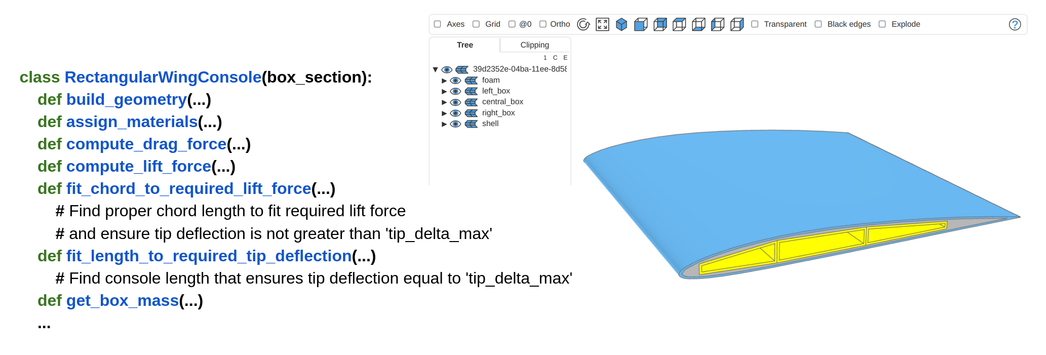
Class Structure
The final model is represented by the RectangularWingConsole class, which aggregates instances of lower-level classes: ThreeChamberBoxedWingSection (that controls the logic for constructing the internal wing geometry), AirfoilSection (for constructing the airfoil section), and Airfoil (a general class that defines airfoil and retrieves airfoil data from SplineCloud).
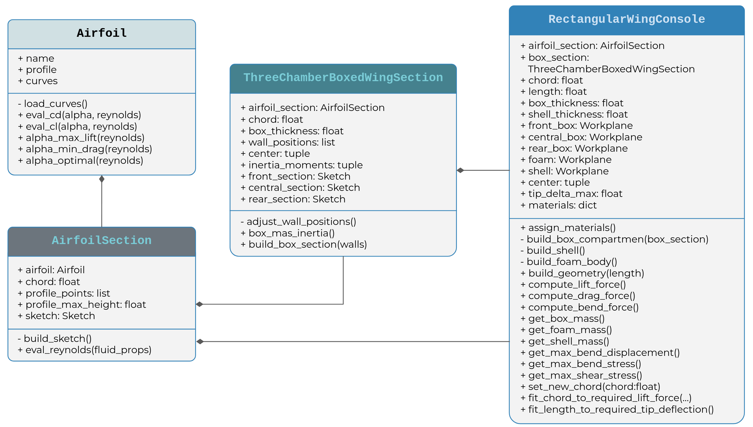
To understand this structure better, let’s dive a bit deeper into the code.
Airfoil Profile And Performance Curves
The basic class is the Airfoil class, which encapsulates all logic for retrieving data on a specific airfoil from SplineCloud: profile points and performance curves. The airfoil collection was built as a JSON file airfoils_collection.json by scraping the SplineCloud API and consists of the following attributes: name, curves, profile, group, and profile_curve.
{
...
"NACA 2408": {
"name": "NACA 2408",
"curves": {
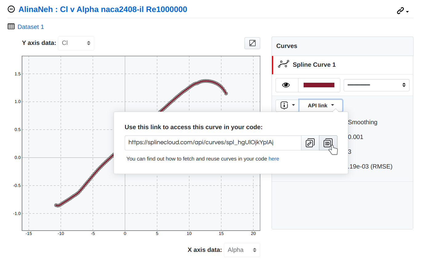
"CL_1000000": "spl_hgUlOjkYpIAj",
"CL_500000": "spl_lgv90Z4SK1xj",
"CL_200000": "spl_J19PJcN0ulRA",
"CL_100000": "spl_h8AGlzL3yvfP",
"CL_50000": "spl_c2lb61287hRg",
"CD_1000000": "spl_50pDtSIs8kvo",
"CD_500000": "spl_PfBbAan4EqIW",
"CD_200000": "spl_HxPXRx2FVdf6",
"CD_100000": "spl_YbSBqImXHLXL",
"CD_50000": "spl_DNH4ib1xqwcb",
"CM_1000000": "spl_rFAmfU4BG1xA",
"CM_500000": "spl_fUt6GFMXf8QW",
"CM_200000": "spl_2qwHYxAXaiw7",
"CM_100000": "spl_OHjEEim0S0tT",
"CM_50000": "spl_mgo5UuMHCXrm"
},
"profile": "sbt_oll9JwctqjUx",
"group": "NACA 4 digit airfoils",
"profile_curve": [
"spl_HUkIezQ5UBNI"
]
},
...
}
The aerodynamic coefficients for airfoils depend on the angle of attack and Reynolds number. The values of the coefficients for the specific values of the Reynolds numbers are obtained by linear interpolation, while dependencies of coefficients against angle of attack are represented by continuous spline curves, built on SplineCloud for each airfoil.
import splinecloud_scipy as scsp
class Airfoil:
def __init__(self, profile_data):
self.name = profile_data["name"]
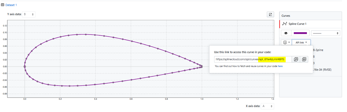
self.profile = scsp.load_subset(profile_data["profile"])
self.profile_data = profile_data
self.load_curves()
...
def interpolated_coefficient(self, alpha, reynolds, coeff):
reynolds_round = int(reynolds*1e-3)*1000
re0, re1 = self.get_reynolds_interval(reynolds_round)
c0 = float(self.curves[f"{coeff}_{re0}"].eval(alpha))
if re0 == re1:
return c0
c1 = float(self.curves[f"{coeff}_{re1}"].eval(alpha))
c = c0 + (reynolds-re0)*(c1-c0)/(re1-re0)
return c
def eval_cl(self, alpha, reynolds):
return self.interpolated_coefficient(alpha, reynolds, "CL")
def eval_cd(self, alpha, reynolds):
return self.interpolated_coefficient(alpha, reynolds, "CD")
def eval_cm(self, alpha, reynolds):
return self.interpolated_coefficient(alpha, reynolds, "CM")
def load_curves(self):
self.curves = {}
for curve_name, curve_uid in self.profile_data["curves"].items():
self.curves[curve_name] = scsp.load_spline(curve_uid)
def cl_to_cd(self, alpha, reynolds):
return float(self.eval_cl(alpha, reynolds)) / float(self.eval_cd(alpha, reynolds))
def cd_to_cl(self, alpha, reynolds):
return 1 / self.cl_to_cd(alpha, reynolds)
The logic for constructing a sketch of the airfoil section and scaling the airfoil to the required chord size is separated in the AirfoilSection class. Basic and miscellaneous methods for airfoil geometry construction and analysis are defined in this class. Here, custom profile approximation methods are declared to obtain a smooth curve. The SciPy method splprep is used to build a parametric spline inside the _bspl_profile_approx method. The main idea in this approach is to obtain a smooth spline, avoiding overfitting. This is done by selecting a smoothing factor s=2e-5 and increasing the weight of the point at the leading edge by 20.
class AirfoilSection:
def __init__(self, airfoil, chord=1000, thicken_sharp_tail=True):
self.airfoil = airfoil
self.chord = chord
self._setup_profile(thicken_sharp_tail)
self.sketch = self.build_sketch()
self.cm = self.get_profile_center_of_mass()
...
def _setup_profile(self, thicken_sharp_tail):
profile_points = self.airfoil.profile.to_numpy()
t, c, k = self._bspl_profile_approx(profile_points)
self.profile_tck = t, c*self.chord, k
self.profile_points = [tuple(p) for p in profile_points*self.chord]
self._setup_profile_curves()
def _bspl_profile_approx(self, profile_points, s=2e-5, k=3):
xvals = [p[0] for p in profile_points]
yvals = [p[1] for p in profile_points]
## set weights to critical profile points
weight_mod = lambda x: 20 if x==0.0 else (5 if x==1.0 else 1)
weights = list(map(weight_mod, xvals))
tck, u = splprep([xvals, yvals], s=s, k=k, w=weights)
t, c, k = tck
cx, cy = c
## adjust spline start and end points to match corresponding profile points
cx[0], cy[0] = profile_points[0]
cx[-1], cy[-1] = profile_points[-1]
return t[k:-k], np.array(list(zip(cx, cy))), k
Once the smooth spline representation of the airfoil profile is constructed, it has to be scaled to the chord size. This is implemented inside the _setup_profile method. Then, in order to use our spline in CadQuery it has to be recreated as the Open CASCADE (OCC) object. This is done inside the build_occ_spline function using the OCP interface [4].
from OCP.TColgp import TColgp_Array1OfPnt
from OCP.TColStd import TColStd_Array1OfInteger, TColStd_Array1OfReal
from OCP.Geom import Geom_BSplineCurve
def build_occ_spline(knot_vector, control_points, degree):
## assume there are no repeating knots inside
knot_mults = list(map(lambda k: degree+1 if k in (0,1) else 1, knot_vector))
poles = TColgp_Array1OfPnt(1, len(control_points))
for i, cp in enumerate(control_points):
poles.SetValue(i+1, gp_Pnt(cp[0], cp[1], 0))
knots = TColStd_Array1OfReal(1, len(knot_vector))
for i, k in enumerate(knot_vector):
knots.SetValue(i+1, k)
mults = TColStd_Array1OfInteger(1, len(knot_mults))
for i, m in enumerate(knot_mults):
mults.SetValue(i+1, m)
bspl = Geom_BSplineCurve(poles, knots, mults, degree)
return bspl
Having an airfoil spline in the OCC representation allows us to construct a CadQuery Sketch object using this spline:
class AirfoilSection:
...
def build_sketch(self, smooth_profile=True):
if smooth_profile:
bspl_occ = build_occ_spline(*self.profile_tck)
profile_edge = cq.Edge(BRepBuilderAPI_MakeEdge(bspl_occ).Edge())
sketch = cq.Sketch().edge(profile_edge)
else:
sketch = cq.Sketch().spline(self.profile_points)
if self.sharp_tail:
return sketch.assemble()
else:
return sketch.close().assemble()
Of course, you can neglect potential overfitting issues and build a profile spline using the spline method of the CadQuery Sketch class directly, avoiding complex smoothing logic (the option under the ‘else’ condition in the code snippet). But if you have the intention to use the obtained model for further analyses or manufacturing, this may lead to the wavy geometry and wing performance reduction. This issue is discussed here.
However, you can avoid using complex logic for building smoothing curves in _bspl_profile_approx method by pulling the profile curves directly from SplineCloud, then scaling, and converting them to OCC objects in the same way described above.
This approach is explained in the article “Creating a Turbofan Generative Model with CadQuery, Streamlit and SplineCloud” by Maksym Valyn [5]. The benefits are obvious - the profile curves are already built using smoothing techniques and verified manually (no surprises should be expected); no need to apply fitting in code, which speeds up the code execution.
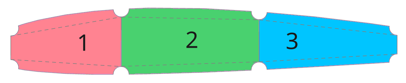
Box Wall Positions Selection
The logic for building internal box compartments and fitting their dimensions into the airfoil is declared in the class ThreeChamberBoxedWingSection. Here, the design problem for maximizing the box height and preserving the manufacturability of the external foam body is solved via an iterative optimization process, where wall positions are adjusted and design conditions are checked.
The important constraint in this problem is to keep the second wall from the left at the region of 0.25 chord, which is close to the center of pressure for the majority of subsonic airfoils. Another internal wall (third from left) we place at the 0.5 chord. Thus, we need to adjust the front and rear walls to fit into the airfoil and preserve meaningful height to avoid geometry construction issues.

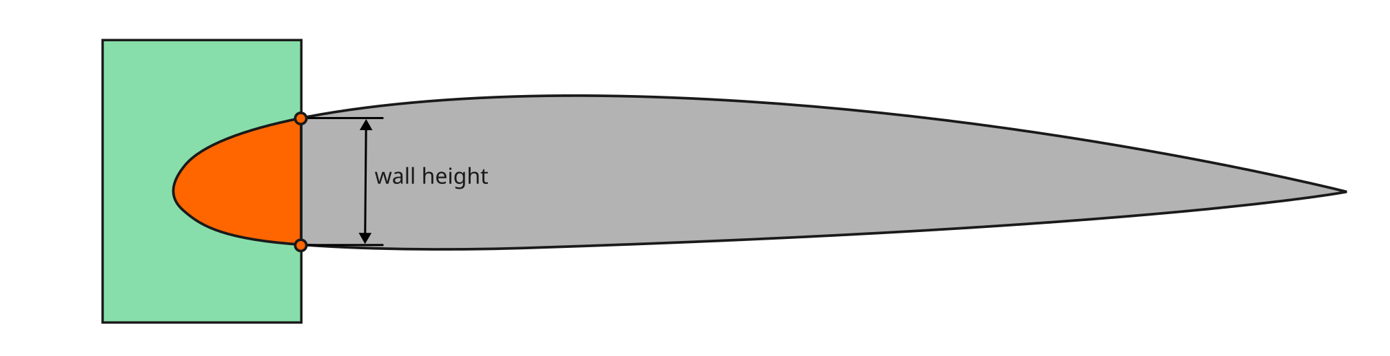
This is implemented in the _adjust_wall_position method that interactively shifts a vertical wall along the airfoil's chord to ensure it intersects the airfoil profile in a region tall enough to fit a structural box (≥ min_wall_height) while maintaining enough foam thickness (min_foam_shell_thickness) around it. It does so by:
- Creating a rectangle with a right edge in the wall position along the chord.
- Intersecting this rectangle with the airfoil shape (mode="i" in .rect()).
- Selecting the vertices on the vertical edge of the resulting geometry (edges("|Y").vertices()).
- Measuring the vertical distance between these two vertices (i.e., wall height).
- Checking whether this height exceeds the required minimum (min_wall_height + foam clearance).
- If not, the wall is nudged incrementally in the right direction until the requirement is met or bounds are exceeded.
class ThreeChamberBoxedWingSection:
def __init__(self, airfoil_section,
wall_positions=None, box_thickness=None, shell_thickness=1, thickness_tol=3):
self.airfoil_section = airfoil_section
self.chord = airfoil_section.chord
if box_thickness:
self.box_thickness = box_thickness
else:
delta_by_height = max(self.airfoil_section.profile_height * 0.08, 1)
delta_by_chord = max(self.chord * 0.01, 1)
self.box_thickness = round(min(delta_by_height, delta_by_chord), thickness_tol)
min_foam_shell_thickness = min(
self.airfoil_section.profile_height * 0.12,
self.box_thickness * 2
)
self.min_foam_shell_thickness = max(min_foam_shell_thickness, 2 * shell_thickness)
self.min_wall_height = self.box_thickness * 3
self.wall_positions = wall_positions or [0.03, 0.25, 0.5, 0.75]
self.adjust_wall_positions()
self.front_section = self.build_box_section(self.wall_positions[:2])
self.central_section = self.build_box_section(self.wall_positions[1:3])
self.rear_section = self.build_box_section(self.wall_positions[2:])
self.box_mass_inertia()
def adjust_wall_positions(self):
self._adjust_wall_position(0, increment=0.02, max_val=self.wall_positions[1]*0.9)
self._adjust_wall_position(3, increment=-0.05, min_val=self.wall_positions[2]*1.1)
def _adjust_wall_position(self, wall_ind, increment=0.05, max_val=1, min_val=0):
correct_offset = False
while not correct_offset:
if self.wall_positions[wall_ind] >= max_val or self.wall_positions[wall_ind] <= min_val:
raise ValueError("Critical wall size have reached before finding solution")
wall_abs_position = self.chord * self.wall_positions[wall_ind]
wall_vertices = (
cq.Sketch()
.polygon(self.profile_points)
.rect(wall_abs_position*2, self.chord, mode="i")
.edges("|Y")
.vertices()
.vals()
)
correct_offset = self._validate_section_wall_height(wall_vertices)
if not correct_offset:
self.wall_positions[wall_ind] += increment
wall_name = {0: 'front', 1: 'second', 2: 'third', 3: 'rear'}
print(f"new {wall_name[wall_ind]} wall position:", self.wall_positions[wall_ind])
def _validate_section_wall_height(self, wall_vertices):
wall_height = abs(wall_vertices[0].Center().y - wall_vertices[1].Center().y)
return wall_height-self.min_foam_shell_thickness*2 >= self.min_wall_height
Box Geometry Construction Logic
The box geometry construction is defined by creating cuts from the airfoil polygon. For this, in the _profile_cut method, we define the airfoil polygon on the new Sketch, and add a rectangle with a center in the box section center. By applying the ‘interception’ modifier, we obtain a cut of the airfoil polygon with vertical edges in the wall positions. Then, we place circles with the radii of the shell offset in the corner vertices, and cut them out. This operation allows us to extract vertical edges that have equal offset from the top and bottom profile curves. Having four vertices, we can build closed hulls for our boxes in the _box_compartment_hull method. These operations are repeated for each of the three pairs of walls, so in the end, we obtain the desired trapezoids, representing box sections, which have the constant offset from the original airfoil profile in the vertices.
def build_box_section(self, walls):
profile_cut = self._profile_cut(self.chord * walls[0], self.chord * walls[1])
return self._box_compartment_hull(profile_cut)
def _profile_cut(self, x1, x2, cut_corners=True):
xc = (x1 + x2) / 2
section_cut = (
cq.Sketch()
.polygon(self.profile_points)
.push([cq.Vector(xc, 0)])
.rect(x2-x1, self.chord, mode="i")
)
if cut_corners:
section_cornercut = (
section_cut
.edges()
.vertices(f">({xc}, 0, 0)")
.circle(self.min_foam_shell_thickness, mode="s")
.edges()
.vertices(f"<({xc}, 0, 0)")
.circle(self.min_foam_shell_thickness, mode="s")
.edges()
)
return section_cornercut
else:
return section_cut
def _box_compartment_hull(self, section):
verts = section.copy().edges('|Y').vertices().vals()
points = [(v.Center().x, v.Center().y) for v in verts]
hull = (
cq.Sketch()
.segment(points[0],points[1])
.segment(points[2],points[3])
.hull()
)
return hull
Wing Console 3D Model Construction
And finally, the 3-dimensional wing console model is represented by the class RectangularWingConsole. This class contains all the logic to build components’ geometry, calculate aerodynamic forces, gravity force, and estimate tip bending deflection.
class RectangularWingConsole:
def __init__(self, root_section, length=1000, box_thickness=None, materials=None,
shell_thickness=1):
self.box_section = root_section
self.airfoil_section = root_section.airfoil_section
self.chord = self.box_section.chord
self.length = length
self.shell_thickness = shell_thickness
self.box_thickness = self.box_section.box_thickness
self.box_material = None
self.shell_material = None
self.foam_material = None
self.assign_materials(materials)
self.build_geometry()
def build_geometry(self):
self.inner_body = self.build_airfoil_body()
self.foam = self.build_foam_body()
self.front_box = self.build_box_compartment(self.box_section.front_section)
self.central_box = self.build_box_compartment(self.box_section.central_section)
self.rear_box = self.build_box_compartment(self.box_section.rear_section)
self.shell = self.build_external_shell()
Let’s first take a look at the geometry construction logic. The method build_airfoil_body constructs a solid airfoil body. This body is used later for constructing the shell and the foam shaper. As you can see, we can obtain this body simply by placing a copy of the airfoil section sketch on a Workplane and extruding it by the length of the console.
def build_airfoil_body(self):
body = (
cq.Workplane()
.placeSketch(self.airfoil_section.sketch.copy())
.extrude(self.length)
)
return body
To build a shell, we need to repeat the same operation, select the top and bottom faces, and call the shell method of the Workplane object.
def build_external_shell(self):
shell = (
cq.Workplane()
.placeSketch(self.airfoil_section.sketch.copy())
.extrude(self.length)
.faces(">Z or <Z")
.shell(self.shell_thickness)
)
return shell
The foam body can be obtained by subtracting the volume of the internal box compartments from the airfoil body. So, we place the inner body on a new Workplane, then place all three box sections together on he same sketch and apply cutThruAll operation.
def build_foam_body(self):
foam = (
cq.Workplane()
.add(self.inner_body)
.center(0,0)
.placeSketch(
self.box_section.front_section,
self.box_section.central_section,
self.box_section.rear_section
)
.cutThruAll()
)
return foam
To build thin-walled box compartments, we can either use a shell() or offset2D approach. Due to the issues with passing negative values to a shell() method, I ended up with the second option (however, this might change as I used an older version of CadQuery before). After extruding a box section, select one of the faces original to the extrusion axis (Z-axis by default), then select wires and add them to the pending geometry and apply the offset2D method, which will create an inset polygon if we pass a negative offset. By cutting it through all box body, we end up with the box shell.
def build_box_compartment(self, box_section):
box = (
cq.Workplane()
.placeSketch(box_section)
.extrude(self.length)
.faces(">Z")
.wires()
.toPending()
.offset2D(-self.box_thickness)
.cutThruAll()
.clean()
)
return box
Aerodynamic and Gravity Loads Evaluation
Besides geometry creation methods, the RectangularWingConsole class has methods to evaluate lift and drag forces, which are essential for preliminary analysis. These methods rely on simplified assumptions about uniform lift distribution along the wing span, which are not correct, and will be fixed in future work. However, this simplification gives a way to understand basic principles.
def compute_lift_force(self, alpha, fluid_props, compute_weight_load=True,
load_factor=1, g=STANDARD_GRAVITY):
console_weight = self.get_console_mass() * g * load_factor
reynolds = self.airfoil_section.eval_reynolds(fluid_props)
cl = self.airfoil_section.airfoil.eval_cl(alpha, reynolds)
lift_force = fluid_props.dynamic_pressure * cl * (self.chord * self.length * 1e-6)
if compute_weight_load:
lift_force = lift_force - console_weight
return lift_force, self.length / 2
def compute_drag_force(self, alpha, fluid_props):
reynolds = self.airfoil_section.eval_reynolds(fluid_props)
cd = self.airfoil_section.airfoil.eval_cd(alpha, reynolds)
drag_force = fluid_props.dynamic_pressure * cd * (self.chord * self.length * 1e-6)
return drag_force
The aerodynamic load is calculated via the airfoil properties, while the calculation of the gravity load requires the value of the wing console mass. To calculate the mass, we can use the CadQuery methods to evaluate each component volume, which we can then multiply by the material density.
def get_components_mass(self, components, material):
volume = 0
for c in components:
volume += c.solids().vals()[0].Volume()
return volume * (1e-3)**3 * material.density
def get_box_mass(self):
return self.get_components_mass(
[self.front_box, self.central_box, self.rear_box], self.box_material
)
def get_foam_mass(self):
return self.get_components_mass([self.foam], self.foam_material)
def get_shell_mass(self):
return self.get_components_mass([self.shell], self.shell_material)
def get_console_mass(self):
box_mass = self.get_box_mass()
foam_mass = self.get_foam_mass()
shell_mass = self.get_shell_mass()
return box_mass + foam_mass + shell_mass
Wing Rigidity And Strength Analysis
Now, once we can calculate the loads on the wing console, we can estimate its rigidity and strength. As mentioned before, we do not rely on FEM, and since we made an assumption that only box withstands all loads, in order to calculate console bending, we need to be able to evaluate the moments of inertia of the compound box section.
This calculation is implemented in the ThreeChamberBoxedWingSection class in the box_mass_inertia() method. Here, instead of defining our own numerical method to calculate moments of inertia of the complex box structure, we can exploit the OCC built-in methods. To do this, we need to create a face of the compound box shells. Basically, we just need to unite all shells and select the bottom face. Then, convert this face to OCC face, create a GProp_GProps object, and pass it along with the OCC face to the SurfaceProperties_s method of the BRepGProp class.
Ugly?
Yes, and this is why high-level wrappers like CadQuery are there - to replace clumsy OCC wrappers with user-friendly interfaces. Unfortunately the ability to calculate inertia moments via CadQuery interface is not implemented yet, but I think it will be there at some point in time (here is the corresponding issue that I created on GitHub).
def box_mass_inertia(self):
from OCP.GProp import GProp_GProps
from OCP.BRepGProp import BRepGProp
...
box = (
cq.Workplane()
.union(front_box)
.union(central_box)
.union(rear_box)
)
box_section = box.faces("<Z")
box_section_occ = box_section.toOCC()
properties = GProp_GProps()
BRepGProp.SurfaceProperties_s(box_section_occ, properties)
matrix_of_inertia = properties.MatrixOfInertia()
Ixx, Iyy, Izz = (
matrix_of_inertia.Value(1,1),
matrix_of_inertia.Value(2,2),
matrix_of_inertia.Value(3,3)
)
self.inertia_moments = Ixx, Iyy, Izz
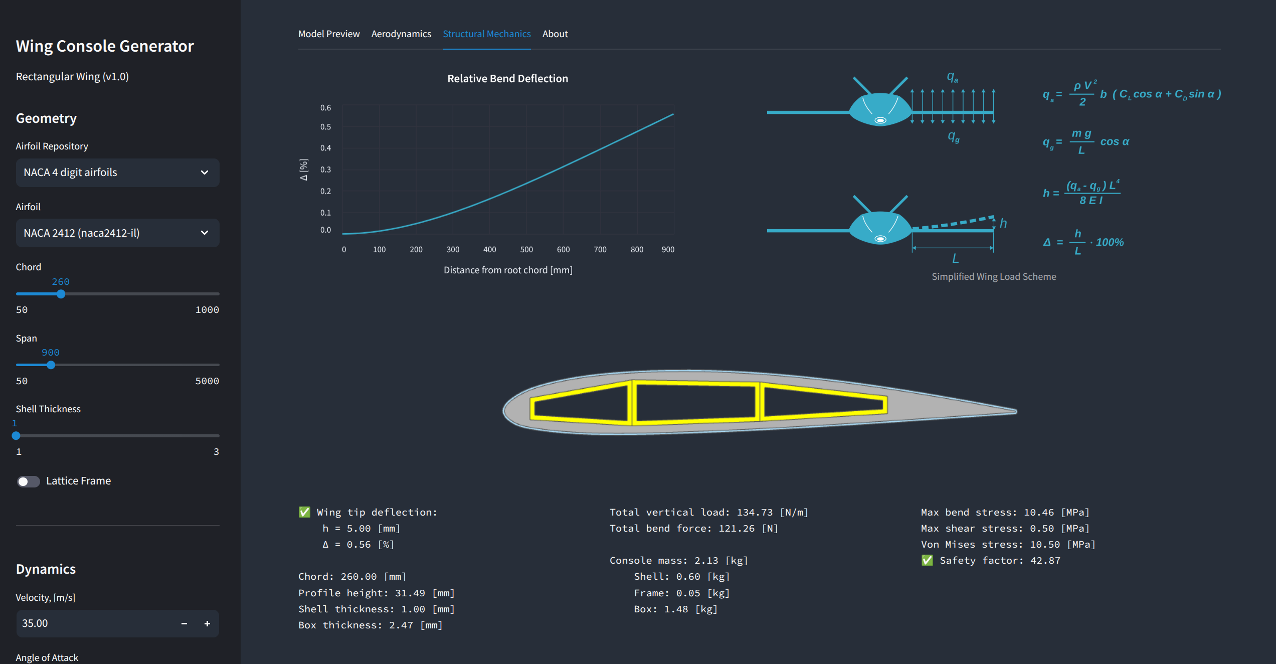
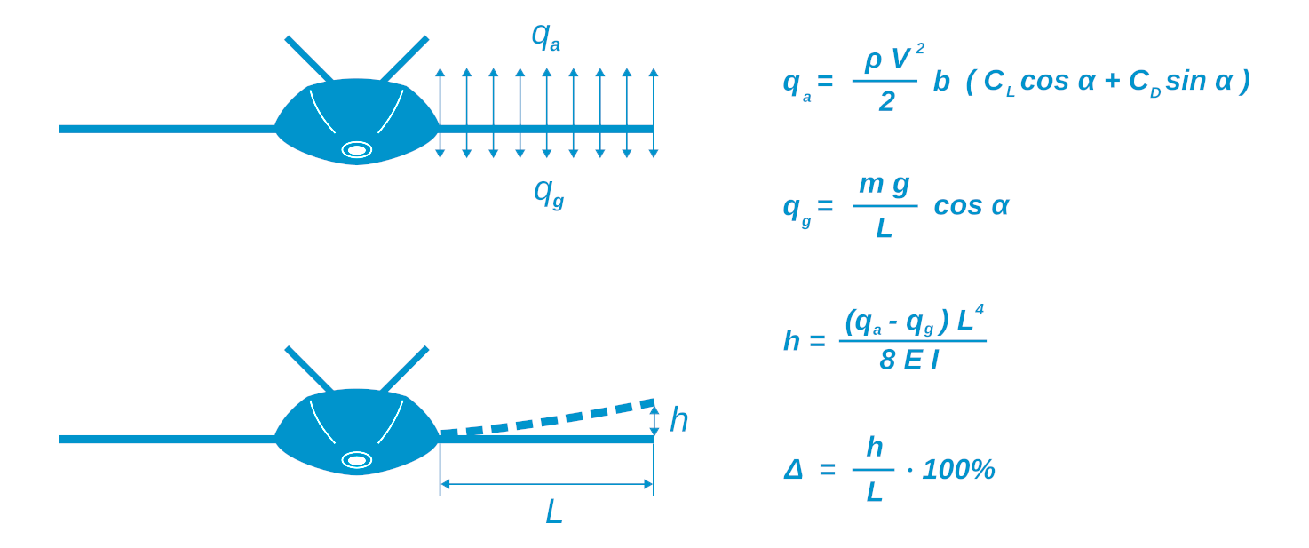
Finally, once we can compute the box section moments of inertia, we can estimate the tip displacement using a simple formula for the beam with constant section:
Here, qa - aerodynamic load, qg - gravity load, L - console length, E - box material elastic modulus, I (Ixx in the code) - box section moment of inertia relative to the horizontal axis.
Along with the moments of inertia calculation, you may find the logic for calculating maximum section offset from the center, as well as the first moments of area. These properties of the box section are used in calculating normal and shear stresses.
def get_max_bend_displacement(self, load):
Ixx, Iyy, Ixy = self.box_section.inertia_moments
nu_max = (load * (self.length*1e-3)**4)/(8 * self.box_material.tensile_modulus * Ixx * (1e-3)**4)
return nu_max * 1e3 ## [mm]
def get_max_bend_stress(self, force):
Ixx, Iyy, Ixy = self.box_section.inertia_moments
bend_moment = force * (self.length * (1e-3)) / 2
stress = bend_moment * self.box_section.max_y_offset*(1e-3) / (Ixx*(1e-3)**4) ## Pa
return stress
def get_max_shear_stress(self, force):
Ixx, Iyy, Ixy = self.box_section.inertia_moments
Qtop = self.box_section.Qtop
Qbottom = self.box_section.Qbottom
t = self.box_thickness * 6 * 1e-3
top_stress = force * Qtop * (1e-3)**3 / (t * Ixx*(1e-3)**4) ## Pa
bottom_stress = force * Qbottom * (1e-3)**3 / (t * Ixx*(1e-3)**4) ## Pa
return max(top_stress, bottom_stress)
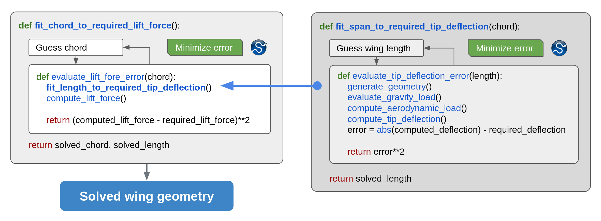
Solving the Wing Model
Now, since we have all the prerequisites for calculating loads on the wing and estimating its bending under these loads automatically, we can set up the iterative process for finding the required wing console size to satisfy two constraints:
- required excess lift force (total lift force minus wing console weight);
- restricted relative tip displacement (ratio of the absolute tip displacement to the console length).
This is implemented in this project via two nested 1-dimensional solvers. The internal method fit_length_to_required_tip_deflection solves for the console length with the fixed chord that satisfies the relative tip deflection. The external method fit_chord_to_required_lift_force solves for the wing console chord that satisfies the excess lift force, and calls fit_length_to_required_tip_deflection on each iteration. Both solvers rely on the absolute error minimization approach using methods of the SciPy optimize module.
Probably, the nested solver scheme is not the best possible strategy, but sufficient for this simple example. You can play with multiparameter optimization approaches using SciPy, or maybe you can try out other libraries, like NLopt. And I think there is great potential in using OpenMDAO here. Let me know if you have ideas on how this can be implemented.
Typically, the described solver converges within 5-10 minutes on my laptop for a single input, however, this may be different on your machine. The slowest operations are CAD operations, and this is the price we pay for a high-level interface to a low-level OpenCASDADE kernel. The significant boost here can be achieved by implementing a surrogate modeling approach, to avoid repetitive creation of geometry. This is a work in progress, and I will write about the results in the next article.
Automating Design Space Exploration
Once we have the ability to solve the wing model against the main geometric parameters - chord and span (length), we can automatically iterate through all airfoils in the knowledge base and choose the best option. The simple criteria here could be the wing weight or the lift-to-weight ratio. Of course, in your study, you can think of additional objective functions, like the maximal internal volume of the box compartments (to fill them with more propellant), or minimal drag, or maximal velocity range, or something else.
A basic analysis for three airfoils was performed for demo purposes: NACA 2408, NACA 2410 and NACA 2412. Compared to traditional interactive design + FEM analysis, that requires lots of manual interactions, the generative approach significantly reduces the time for the full cycle of generation and evaluation. Generation and analysis of the three options took my laptop just a couple of hours to iterate through several payload masses for three airfoils. I can only imagine how many days I would have spent doing it the traditional way.

The results show that the thin profile performs better - it has lower drag and, higher lift-to-weight ratio. This is not exactly correct, since we made an assumption about uniform lift distribution. For this reason, our solver converges to smaller aspect ratios for thin profiles and higher aspect ratios for thicker profiles. This trend might be different once we introduce a correct lift distribution law (future work).
Development and Debugging Approach
When you work with 3D modeling tools, you need to have visual feedback. Fortunately, there are plenty of ways to visualize the results of generated models. You can read about all of them on the CadQuery documentation page [6], but basically, you can choose between the built-in visualization options - CQviewer or notebook rendering, and side-projects, like CQ-Editor and Jupyter-CadQuery [7]. Personally, due to my habit of running experiments in the Jupyter Notebook I prefer using the last option. Jupyter-CadQuery is a powerful rendering tool that outputs a minimalistic CAD viewer with several helpful display options in your notebook cell output, so you have real CAD modelling experience integrated in your notebook.
It is important to mention here that there are several completely different approaches to modeling using CadQuery - traditional flow method, which utilizes chained method calls that you have seen in my code, and a new free function approach, which I think is a simpler and more flexible approach [8]. And there is also a fork of CadQuery called build123d that uses context manager approach for the geometry creation [9].

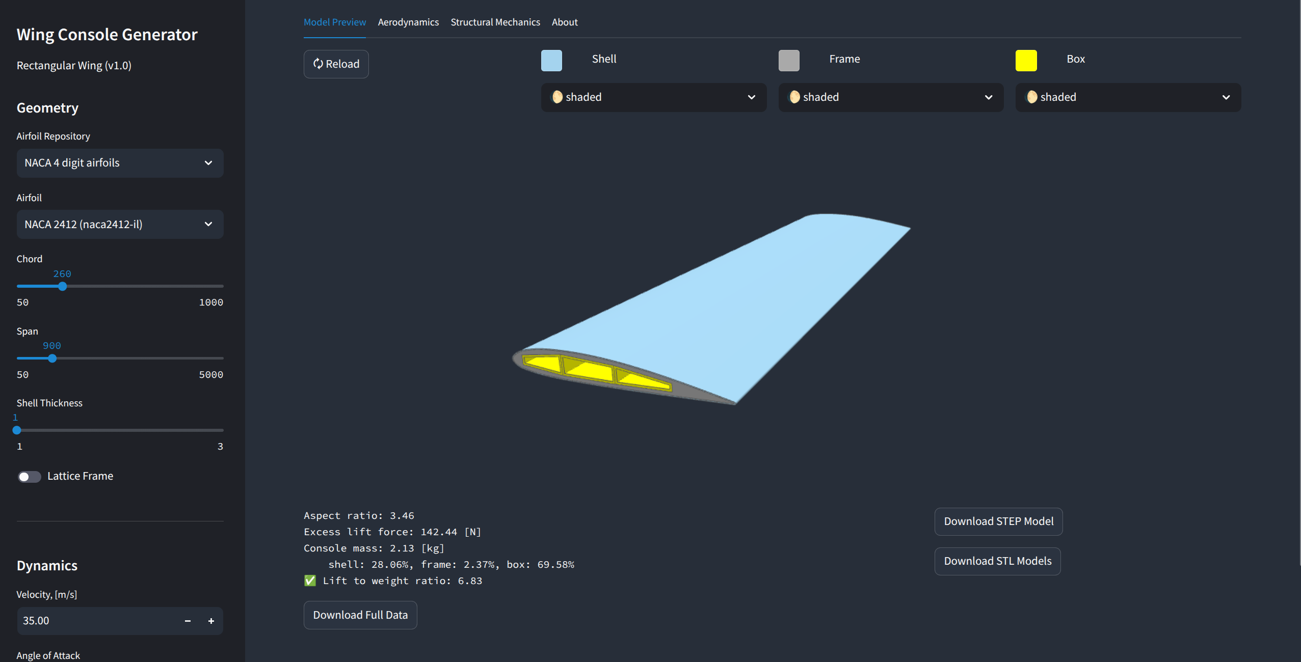
Building a Wing Generator Web Application
We took a deep dive into building the generative model of the wing using Knowledge-Based Engineering principles, SplineCloud as an external knowledge base and open-source libraries for Python. The object-oriented programming approach allowed us to build programmable interfaces to our model: we can instantiate it with initial parameters, assign materials, rebuild it based on new inputs, and solve it for the design constraints. And with the use of Jupyter Notebook (or JupyterLab), we can run numerical experiments and analyze results in the browser with graphical output. But wouldn’t it be nice to have a classical graphical interface to our model, so folks with no programming experience can use it and benefit from the work we've done?
Hell yeah! And this can be done with little blood using Streamlit - an amazing open-source framework for building interactive web applications with Python. With the help of Streamlit [10], we can end up with a complete expert system that we can deploy anywhere. The architecture of such an expert system consists of three components: a reusable knowledge base, a generative model, and a web interface.

However, explaining its structure here would be overkill for a blog post. So I decided to bring it to a separate post. However, here you can access its source code.
And the live app is deployed here.
Conclusions
Well, if you read down to here, I assume you find this article interesting and maybe even inspiring.
Wrapping up: this example demonstrates how a generative knowledge-based engineering (KBE) approach can drastically improve early-stage design workflows, especially in aerospace, but with potential far beyond. By combining domain knowledge, rule-based logic, and simplified numerical methods, we automated the conceptual development of a wing console and enabled rapid evaluation of many design alternatives with a significant boost in time saving compared to traditional iterative simulation-based approaches.
The project is built entirely using open-source tools — Python, CadQuery, NumPy, SciPy, and Streamlit (for the graphical user interface to the model). The model leverages the SplineCloud API and its client library for Python for direct reuse of airfoil shape data and aerodynamic performance characteristics in code. Instead of relying on complex and computationally expensive FEM solvers, this project uses custom lightweight algorithms for lift and stiffness estimation, which are much faster while still effective at the conceptual stage.
Some rough assumptions, like uniform lift force distribution along the wing span, limit the applicability of this model. But this can be fixed, since the code is open.
The key takeaway is how we integrate an intuitive user interface with a powerful backend logic. The KBE model encapsulates reusable engineering logic, the knowledge base stores formalized domain knowledge (on airfoils), and the GUI lets users input design parameters and instantly visualize the resulting geometry. This layered structure promotes reusability, clarity, and future extensibility — for instance, the same architecture could be extended to include FEM simulations or more complex parametric geometries.
Overall, this project shows how we can move from manual modeling and repetitive simulations to knowledge-driven automation. It’s not just faster — it’s smarter. And it opens the door to more creative, high-impact engineering work by removing friction from early-stage decision making.
The project source code is available here.
Drop me a message if you want to contribute or have questions.
References
[1] La Rocca, G., & van Tooren, M. J. L. (2007). Knowledge-based engineering for aerospace design. Journal of Aerospace Engineering, 220(4), 419–427, DOI: 10.1243/09544100JAERO592
[2] La Rocca, G. (2012). Knowledge-based engineering: Between AI and CAD – Review of developments and future trends. Computer-Aided Design, 44(1), 166–176, https://doi.org/10.1016/j.aei.2012.02.002
[3] CadQuery on GitHub: https://github.com/CadQuery/cadquery
[4] Python wrapper to OCC: https://github.com/CadQuery/OCP
[5] M. Valyn. (2025) "Creating a Turbofan Generative Model with CadQuery, Streamlit and SplineCloud"
[6] CadQuery Documentation
[7] Jupyter-CadQuery on GitHub: https://github.com/bernhard-42/jupyter-cadquery
[8] A. Urbanczyk, Free Function API for CadQuery, FOSDEM 2025
[9] build123d on GitHub: https://github.com/gumyr/build123d
[10] Streamlit on GitHub: https://github.com/streamlit/streamlit