GGGEARS
Gggears is an open-source python package for modeling ... you guessed it... gears. It started out as an exercise in object oriented python, but grew in ambition to enable model-generation of all kinds of gears.
Although, while dreaming of some lofty goals of modelling all gears, gggears currently offers a modest selection to its users: involute spur, cycloid, helical, bevel and inside-ring gears.
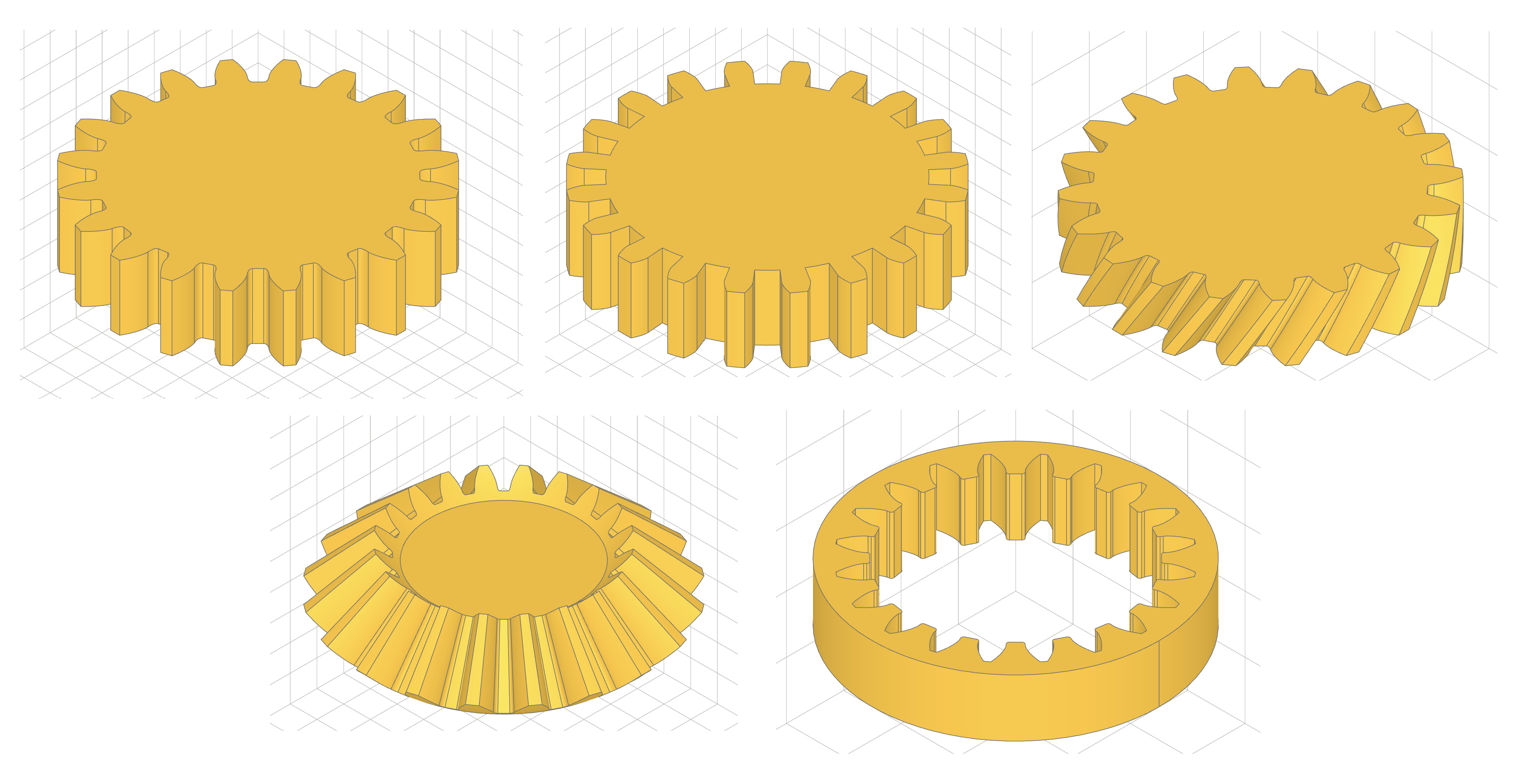
Gear types in gggears: Spur, cycloid, helical, bevel, ring
Gggears also it provides utilities for positioning gears to mesh properly. Here's an example of the python workflow:
from gggears import *
from ocp_vscode import show

num_teeth_1 = 41
num_teeth_2 = 12
cone1, cone2 = cone_angle_from_teeth(num_teeth_1, num_teeth_2)
gear1 = BevelGear(num_teeth_1, height=6, cone_angle=cone1)
gear2 = BevelGear(num_teeth_2, height=6, cone_angle=cone2)

# setting up position of gear2
gear2.mesh_to(gear1, target_dir=UP)

# spline calculations and CAD Part-object conversion
part = gear1.build_part()
part2 = gear2.build_part()

# display gears
show_all()
Example Python code using gggears
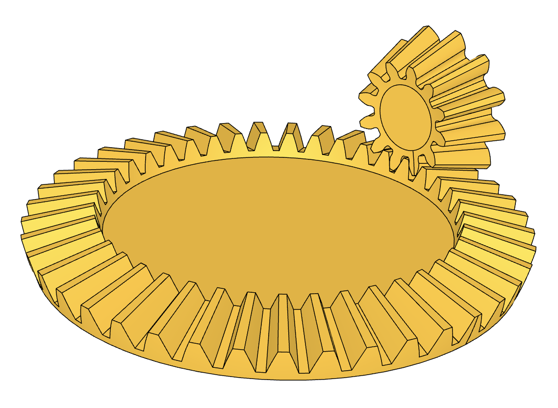
Meshing straight bevel gears
(output of the above code)
The package is dependent on the python-based CAD modeling framework called Build123d, and visualization comes from OCP_Viewer. The models can be exported to a variety of 3D model formats (STEP, STL, etc.)
So is there anything special about this project?
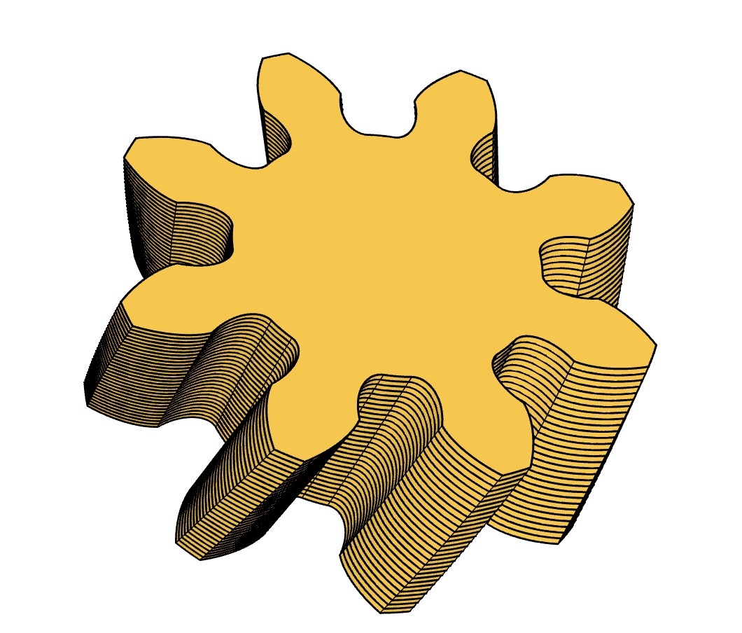
Gggears has a custom gear-generator engine under the hood. Driven by the frustration from limitations and bugs of scripted CAD programs, I decided to build the complete computation pipeline from scratch with numpy and scipy. Gggears starts with gear-parameters, and crunches numbers and formulae until it arrives at surface-spline control points. Then those control points are passed to the CAD kernel for further processing and display.
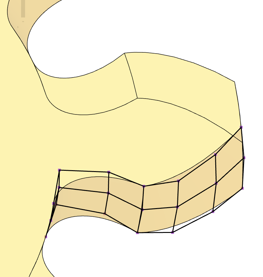
Surface spline control points of a tooth-flank
This gives freedom and control to design all kinds of (sometimes wacky) gear features that would otherwise be inconvenient or impossible to do with common CAD modeling steps.
One example is the practice of ‘crowning’, which cannot be produced by simple geometric construction steps.
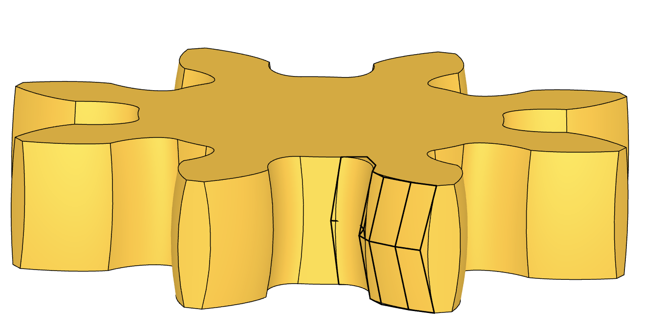
Crowning
Crowning is when the gear flanks are ground into a slight barrel-shape. This is to avoid contact-stress concentrating near the edges if the gear axes are not perfectly parallel. The figure is vastly out of proportion though, this feature is meant to be microns deep and not visible at first glance.
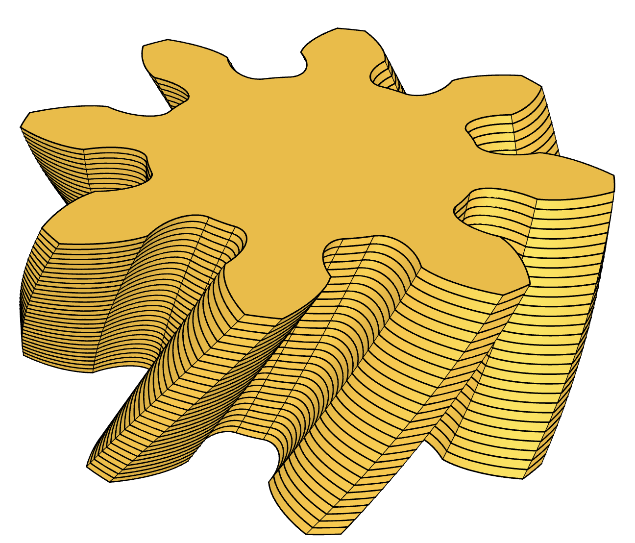
The custom toolchain also lets me commit sins like this:
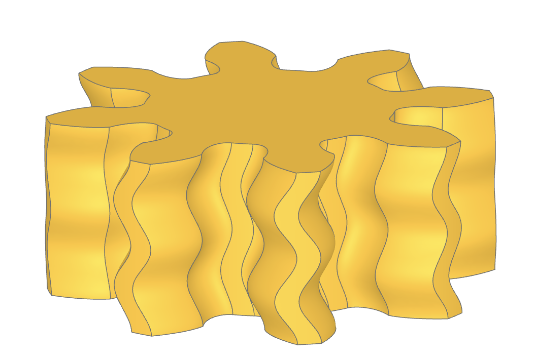
A (co)sine gear
It is not without limitations of course. What's stopping me from creating hypoid gears is the lack of understanding their shape...
But also, the current construction method doesn't quite work for the most complex gears. My method is based on mathematically ideal involute and trochoid curves, only their parameters are freely variable as a function of progress in the ‘z’ direction. Once a sufficient number of analytical curves are calculated, splines are fit onto them so that the shape can be transferred into the CAD library.
Real-world gears aren’t always easy (or possible) to represent with analytic functions. Gears are manufactured by taking a cutting tool with a certain shape, and moving it along a 3D path relative to the blank material to shape the gear flanks. This can get quite complicated with e.g. spiral-bevel and hypoid gears. These shapes are inherently 3D and may not have a solution in terms of involute or sinusoid functions with varying parameters.
The simple 2D first and then 3D approach just does not cut it.
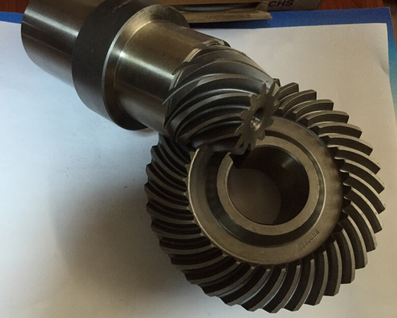
Hypoid gear set
Still, I will continue to use gggears as a learning tool and coding practice, and who knows, maybe some day it might even be useful for someone.
Check out gggears if you're interested.