Quadcopter Frame Design Parameters
About
Add a short description of your repository
Wiki
Structural analysis of the quadcopter frames of various sizes
This repository contains the results of the structural analyses of the quadcopter frame of various sizes. Obtained results in the form of functional relations of the frame parameters can be used to simplify preliminary design calculations of quadcopters.
Frame Structure
The main frame structure consists of flat elements made of carbon-epoxy laminate. These are: arms, stiffener stripes, hardware mounting plates (central plates), and motor mounting plates. The top and middle hardware plates are joined with aluminum spacers (tubes). Similar spacers are used to joint motor mounting plates, that also hold stiffener stripes. The main view of the frame is shown in Figure 1.
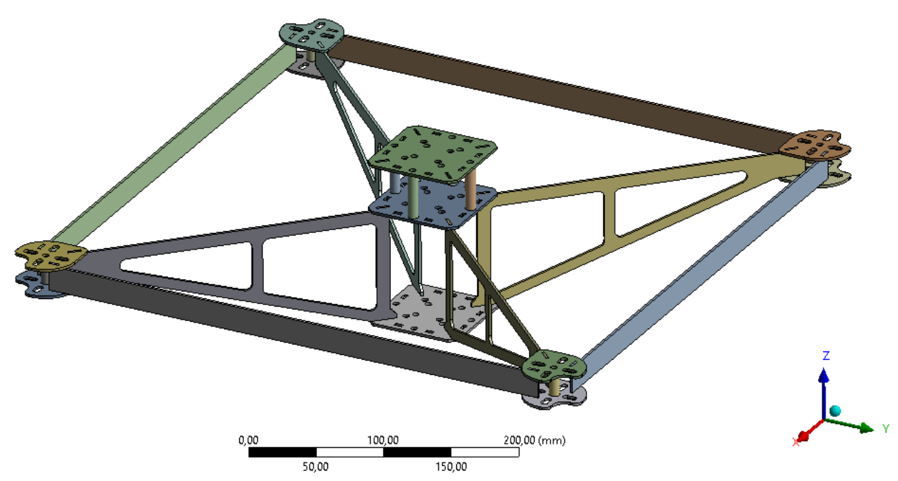
Figure 1 - Main view of the frame (D = 600 mm, s = 2 mm)
Material Properties
The material of the main structure of the frame is epoxy/carbon fiber laminated composite LY5/5 [+35; –35; 0; +35; –35] [1].
Fiber: Unidirectional carbon fiber, Toray’s Torayca T700S-12 k, was employed to lay-up composite laminates as a reinforcing agent [1].
Matrix: Araldit LY 5052 [1].
Next mechanical and physical properties of the composite material were considered for all frame elements:
E = 4,57*1010 Pa – tensile modulus;
µ = 0,32 – Poisson’s ratio;
ρ = 1500 kg/m3.
Problem statement
In order to facilitate selection of the proper frame during design calculations, a number of static structural analyzes of the frame modifications were conducted for two fixed values of the structural element thickness - 2mm and 3mm, and a range of diagonal frame dimensions D:
- D = 400 mm,
- D = 600 mm;
- D = 800 mm;
- D = 1000 mm;
- D = 1200 mm;
- D = 1400 mm.
Where D is the diagonal distance between opposite motor mounting axes.
The solution model of the frame consists of the frame, two point masses, which are modeling electronic components and drone payload (camera), and distributed mass to model a battery placed in the bottom compartment.
The mass of electronic components is 0,3 kg.
The mass of the camera is 0,3 kg.
The mass of the battery is 3 kg.
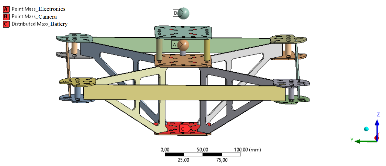
Figure 2 – Main view of the frame (D = 400 mm, s = 2 mm)
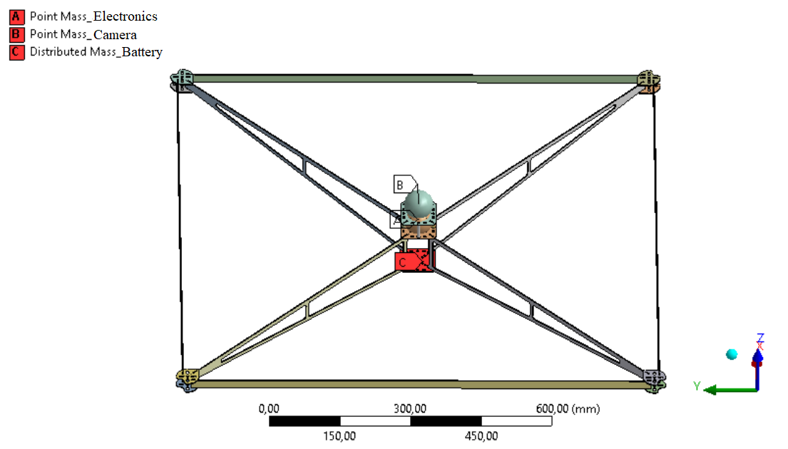
Figure 3 – Main view of the frame (D = 1400 mm,s= 2 mm)
Boundary Conditions
The frame is fixed in the four mounting holes in the bottom hardware plate of the frame.
The forces are applied to the central motor mounting holes located on the motor mounting plates, simulating the action of lifting forces of the motors.
The calculations were carried out with a stepwise increase of loads in a range from 20 N to 400 N with the step of ΔF = 20 N.
Boundary conditions are the same for all study cases.
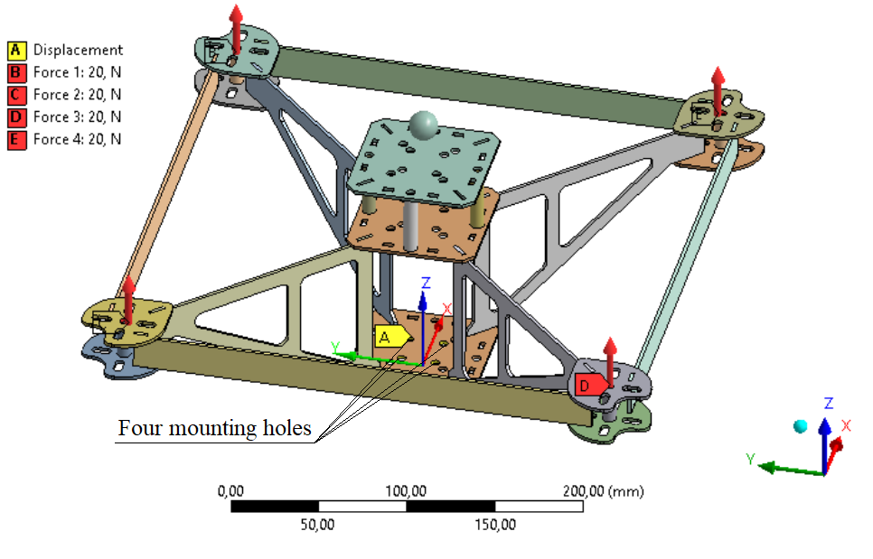
Figure 4 – Solution scheme of the frame (D = 400 mm, s = 2 mm)
Finite Element Model
The finite-element model (FE-model) consists of SOLID-types finite elements with a minimum element size of 1 mm.
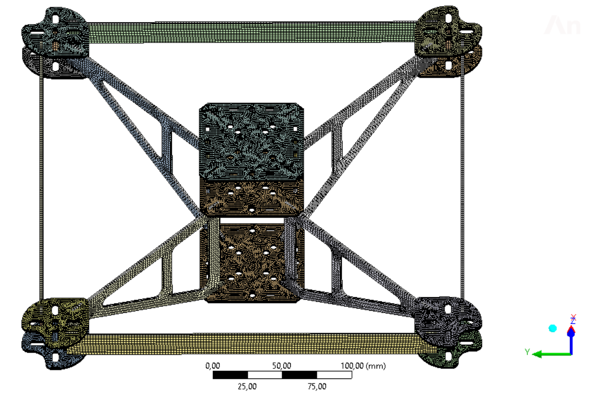
Figure 5 - Finite element model of the frame (D = 400 mm, s = 2 mm)
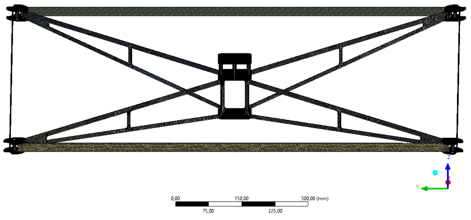
Figure 6 - Finite element model of the frame (D = 1400 mm, s = 2 mm)
Solution Results
Solution results are given in the spreadsheets:
Frame bearing capacity.xlsx
Frame deformation study results.xlsx
Single force study results (F=20N).xlsx
Displayed in the figures below are diagrams showing the gradients of the main solution results for two study cases. The total applied load on each of these frames is 1200 N, distributed as four forces of 400 N each, acting at the motor mounting locations. The black lines in the figures represent the undeformed state of the structure, while the deformed state is scaled up for better visualization.
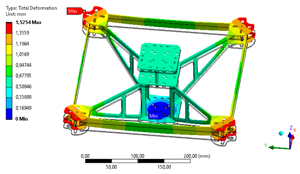
Figure 7 – Total Deformation of the frame (D = 400 mm, s = 2 mm)
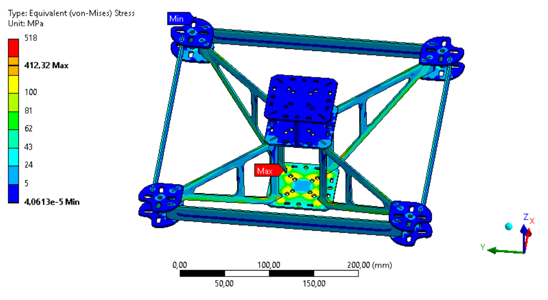
Figure 8 – Equivalent stress of the frame (D = 400 mm, s = 2 mm)
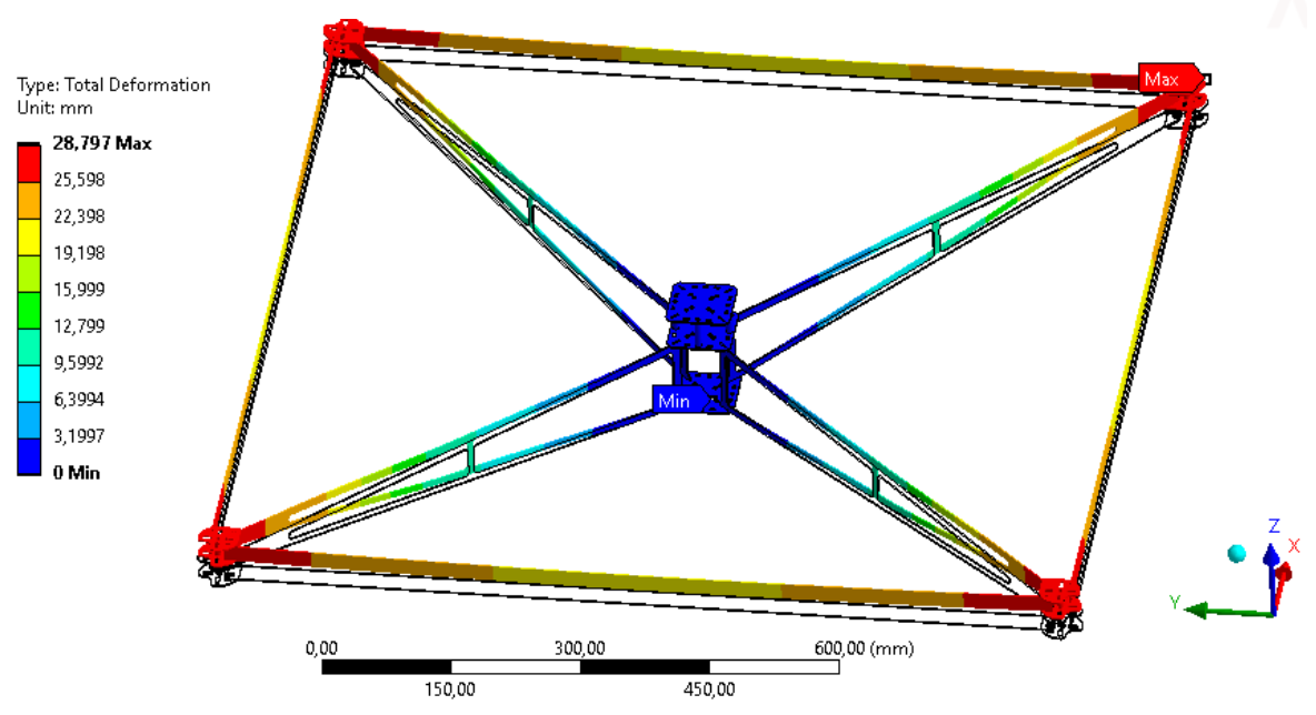
Figure 9 – Total Deformation of the frame (D = 1400 mm, s = 2 mm)
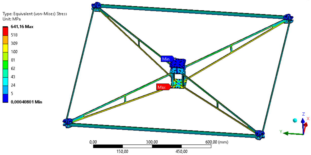
Figure 10 – Equivalent stress of the frame (D = 1400 mm, s = 2 mm)
Results of bearing capacity analysis of each frame size and structural element thickness are presented in the file "Frame bearing capacity.xlsx". The datasets are grouped by the element thickness and contain data on the force that leads to the motor axes inclination ('Rotation angle' column) in ~0.5 degrees.
These data are obtained from the raw simulation data that represents frame deformation for various loads, collected in the spreadsheet 'Frame deformation study results.xlsx', and grouped into datasets by the frame size and structural element thickness. For example ‘D=400mm; s=2mm' means the frame diagonal is 400 mm and the thickness of the structural elements is 2 mm.
The simulations were carried out with a stepwise increase of loads acting on the frame. The solution contains the next computed parameters for each frame size:
- frame mass;
- equivalent stress in carbon elements;
- equivalent elastic strain of carbon elements;
- rotation angle of the motor axis;
- normal deformation of the motor mounting plate.
The datasets of the load-bearing capacity analysis of the frame contains two additional columns:
- ‘Δ from D, %’ – this parameter characterizes the percentage of normal deformation to the frame size;
- ‘H = Force/Weight’ – this parameter characterizes the ratio of the maximum bearing capacity to the weight of the frame.
Several criteria for determining the load bearing capacity of the frame were considered:
- allowable stress of carbon elements of the frame;
- Δ = 0,5%∙D – allowable deformation of the frame is 0,5% of diameter;
- allowable rotation angle is 0,5°;
- allowable rotation angle is 1,0°.
The last spreadsheet ' Single force study results (F=20N).xlsx' contains simulation results for a single load value of 20N for various frame sizes.
The datasets titled ‘Parameters vs Diameter’ define the relations of the next frame parameters to the frame size for fixed load and for two values of structural elements thickness:
- mass vs frame size;
- equivalent stress of carbon elements vs frame size;
- equivalent elastic strain of carbon elements vs frame size;
- rotation angel vs frame size;
- normal deformation vs frame size;
- Δ from D vs frame size;
- H = Force/Weight vs frame size.
Conclusions
The analyses of the simulation results showed that the most reasonable criterion for determining the frame bearing capacity is the criterion of allowable motor axis inclination angle (induced by the frame deformation), which was set to 0,5°.
References
- Mechanical Properties of Carbon Fiber/Epoxy Composites: Effects of Number of Plies, Fiber Contents, and Angle-Ply Layers - Hossein Rahmani, Shohreh Saffarzadeh-Matin, Seyed Heydar Mahmoudi Najafi, Alireza Ashori. - Polymer Engineering and Science, November 2014. - DOI: 10.1002/pen.23820.
Structural analysis of the quadcopter frames of various sizes
This repository contains the results of the structural analyses of the quadcopter frame of various sizes. Obtained results in the form of functional relations of the frame parameters can be used to simplify preliminary design calculations of quadcopters.
Frame Structure
The main frame structure consists of flat elements made of carbon-epoxy laminate. These are: arms, stiffener stripes, hardware mounting plates (central plates), and motor mounting plates. The top and middle hardware plates are joined with aluminum spacers (tubes). Similar spacers are used to joint motor mounting plates, that also hold stiffener stripes. The main view of the frame is shown in Figure 1.
Figure 1 - Main view of the frame (D = 600 mm, s = 2 mm)
Material Properties
The material of the main structure of the frame is epoxy/carbon fiber laminated composite LY5/5 [+35; –35; 0; +35; –35] [1].
Fiber: Unidirectional carbon fiber, Toray’s Torayca T700S-12 k, was employed to lay-up composite laminates as a reinforcing agent [1].
Matrix: Araldit LY 5052 [1].
Next mechanical and physical properties of the composite material were considered for all frame elements:
E = 4,57*1010 Pa – tensile modulus;
µ = 0,32 – Poisson’s ratio;
ρ = 1500 kg/m3.
Problem statement
In order to facilitate selection of the proper frame during design calculations, a number of static structural analyzes of the frame modifications were conducted for two fixed values of the structural element thickness - 2mm and 3mm, and a range of diagonal frame dimensions D:
- D = 400 mm,
- D = 600 mm;
- D = 800 mm;
- D = 1000 mm;
- D = 1200 mm;
- D = 1400 mm.
Where D is the diagonal distance between opposite motor mounting axes.
The solution model of the frame consists of the frame, two point masses, which are modeling electronic components and drone payload (camera), and distributed mass to model a battery placed in the bottom compartment.
The mass of electronic components is 0,3 kg.
The mass of the camera is 0,3 kg.
The mass of the battery is 3 kg.
Figure 2 – Main view of the frame (D = 400 mm, s = 2 mm)
Figure 3 – Main view of the frame (D = 1400 mm,s= 2 mm)
Boundary Conditions
The frame is fixed in the four mounting holes in the bottom hardware plate of the frame.
The forces are applied to the central motor mounting holes located on the motor mounting plates, simulating the action of lifting forces of the motors.
The calculations were carried out with a stepwise increase of loads in a range from 20 N to 400 N with the step of ΔF = 20 N.
Boundary conditions are the same for all study cases.
Figure 4 – Solution scheme of the frame (D = 400 mm, s = 2 mm)
Finite Element Model
The finite-element model (FE-model) consists of SOLID-types finite elements with a minimum element size of 1 mm.
Figure 5 - Finite element model of the frame (D = 400 mm, s = 2 mm)
Figure 6 - Finite element model of the frame (D = 1400 mm, s = 2 mm)
Solution Results
Solution results are given in the spreadsheets:
Frame bearing capacity.xlsx
Frame deformation study results.xlsx
Single force study results (F=20N).xlsx
Displayed in the figures below are diagrams showing the gradients of the main solution results for two study cases. The total applied load on each of these frames is 1200 N, distributed as four forces of 400 N each, acting at the motor mounting locations. The black lines in the figures represent the undeformed state of the structure, while the deformed state is scaled up for better visualization.
Figure 7 – Total Deformation of the frame (D = 400 mm, s = 2 mm)
Figure 8 – Equivalent stress of the frame (D = 400 mm, s = 2 mm)
Figure 9 – Total Deformation of the frame (D = 1400 mm, s = 2 mm)
Figure 10 – Equivalent stress of the frame (D = 1400 mm, s = 2 mm)
Results of bearing capacity analysis of each frame size and structural element thickness are presented in the file "Frame bearing capacity.xlsx". The datasets are grouped by the element thickness and contain data on the force that leads to the motor axes inclination ('Rotation angle' column) in ~0.5 degrees.
These data are obtained from the raw simulation data that represents frame deformation for various loads, collected in the spreadsheet 'Frame deformation study results.xlsx', and grouped into datasets by the frame size and structural element thickness. For example ‘D=400mm; s=2mm' means the frame diagonal is 400 mm and the thickness of the structural elements is 2 mm.
The simulations were carried out with a stepwise increase of loads acting on the frame. The solution contains the next computed parameters for each frame size:
- frame mass;
- equivalent stress in carbon elements;
- equivalent elastic strain of carbon elements;
- rotation angle of the motor axis;
- normal deformation of the motor mounting plate.
The datasets of the load-bearing capacity analysis of the frame contains two additional columns:
- ‘Δ from D, %’ – this parameter characterizes the percentage of normal deformation to the frame size;
- ‘H = Force/Weight’ – this parameter characterizes the ratio of the maximum bearing capacity to the weight of the frame.
Several criteria for determining the load bearing capacity of the frame were considered:
- allowable stress of carbon elements of the frame;
- Δ = 0,5%∙D – allowable deformation of the frame is 0,5% of diameter;
- allowable rotation angle is 0,5°;
- allowable rotation angle is 1,0°.
The last spreadsheet ' Single force study results (F=20N).xlsx' contains simulation results for a single load value of 20N for various frame sizes.
The datasets titled ‘Parameters vs Diameter’ define the relations of the next frame parameters to the frame size for fixed load and for two values of structural elements thickness:
- mass vs frame size;
- equivalent stress of carbon elements vs frame size;
- equivalent elastic strain of carbon elements vs frame size;
- rotation angel vs frame size;
- normal deformation vs frame size;
- Δ from D vs frame size;
- H = Force/Weight vs frame size.
Conclusions
The analyses of the simulation results showed that the most reasonable criterion for determining the frame bearing capacity is the criterion of allowable motor axis inclination angle (induced by the frame deformation), which was set to 0,5°.
References
- Mechanical Properties of Carbon Fiber/Epoxy Composites: Effects of Number of Plies, Fiber Contents, and Angle-Ply Layers - Hossein Rahmani, Shohreh Saffarzadeh-Matin, Seyed Heydar Mahmoudi Najafi, Alireza Ashori. - Polymer Engineering and Science, November 2014. - DOI: 10.1002/pen.23820.