Rectangular Beam Bending Analyses
About
Add a short description of your repository
Wiki
Rectangular beam bending under static linear load
This repository contains the results of the FEM simulation of a simple rectangular beam bending. Two problems were analyzed:
1) Determination of the steel hollow beam rigidity in relation to its Width (B), Height (H), Thickness (s) and Length (L).
Problem statement: Line pressure acts on the cantilever beam, fixed on one side. Reactions in a place of fixation are equal for all solution cases. Results are presented in the file ‘Bend of rectangular hollow section beam.xlsx’;
2) Determination of the fiberglass hollow beam rigidity in relation to Length (L) and line pressure (q) magnitude for three types of beam sections: 50×100×5mm, 100×200×10mm and 200×400×20mm.
Problem statement: Line pressure acts on the cantilever beam. In this task maximal displacement of the beam is limited to 0,02L and the magnitude of the line pressure corresponds to the beam deformation of 0,02L. Results are presented in the file ‘Longeron (tube) - BENDING - Def=2%.xlsx’.
Solution results for these problems may be used to design various structures, e.g. a longeron of a wing.
Problem 1
Deformations of the steel beam with a rectangular section under line pressure were studied in this problem. Two methods were employed to find a solution. The first approach involved theoretical analysis using this equation:
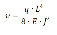
where v – max deformation of the beam, m;
q – line pressure, N/m;
L – length of beam, m;
E – Young`s modulus, Pa;
J – beam section moment of inertia, m4.
The second approach is to apply the Finite Element Method using ANSYS Workbench software.
The solution was found for a linear deformation without accounting for the plasticity of the material.
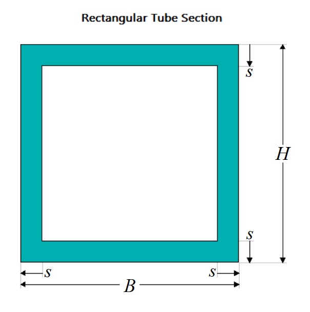
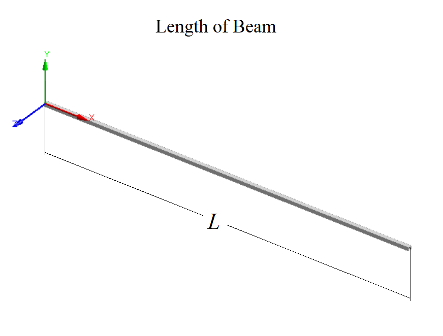
Beam Dimensions
The scheme of the beam section is represented in the figure below.
Material Properties
The material of the beam is Structural Steel with the next characteristics:
E = 2*1011Pa;
µ = 0,3.
Boundary Conditions
The scheme of boundary conditions is represented on the figure below.
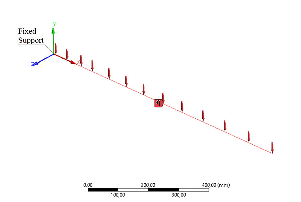
Where ‘q’ is a line pressure.
Gravity wasn’t taken into account.
Finite Element Model
FE-model consists of LINE-type finite elements with a size equal to 1mm.

Solution Results
Solution results of Problem 1 are represented for four cases:
1) ‘Variable Length’ – the length of the beam changes from 500 to 5000 mm while other dimensions are fixed (B = 10 mm, H = 10 mm, s = 1 mm, q = 0,1 N/mm);
2) ‘Variable Width’ – the width of the beam section changes from 5 to 100 mm while other dimensions are fixed (L = 1000 mm, H = 10 mm, s = 1 mm, q = 0,1 N/mm);
3) ‘Variable Height’ – the height of the beam section changes from 5 to 100 mm while other dimensions are fixed (L = 1000 mm, B = 10 mm, s = 1 mm, q = 0,1 N/mm);
4) ‘Variable Thickness’ – thickness of the beam section changes from 1 to 50 mm while other dimensions are fixed (L = 1000 mm, B = 101 mm, H = 101 mm, q = 0,1 N/mm).
One of the examples of the solution results is represented in the figure below. In this figure, we can see deformations of the beam with the next parameters: L = 1000 mm, B = 10 mm, H = 10 mm, s = 1 mm, q = 0,1 N/mm.

Problem 2
Deformations of the fiberglass beam with a rectangular section under line pressure were studied in this problem. Solutions were obtained with the help of the ANSYS Workbench software.
Deformations in ANSYS Workbench were found for the variable beam length, ranging from 1500 to 10000mm, and for three beam section dimensions:
- 50×100×5mm;
- 100×200×10mm;
- 200×400×20mm;
For each study a linear load was selected in such a way, that it should produce a tip deflection of 2% of the beam length based on the next equation:

where q – line pressure, N/m;
E – Young`s modulus, Pa;
J – beam section moment of inertia, m4;
v – max deformation of the beam, m;
L – length of beam, m.
The solution was found for a linear deformation without accounting for the plasticity of the material
The purpose of Problem 2 is to find relations between beam deformations and beam linear load magnitude with the condition that v=0,02L, and compare analytical and numerical results.
Beam Dimensions
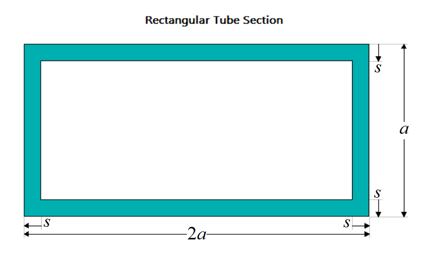
The scheme of the beam section is represented in the figure below.
Material Properties
The material of the beam is Fiberglass STEF-1 with the next characteristics:
E = 2,16*1010Pa;
µ = 0,3.
Boundary Conditions
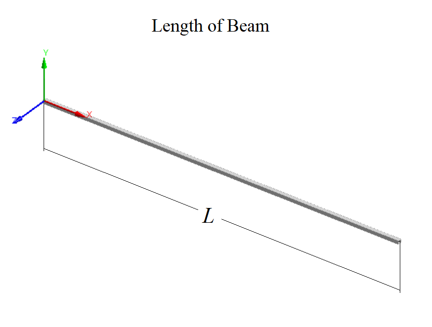
The scheme of boundary conditions is represented in the figure below.

Where ‘q’ is a line pressure.
Gravity wasn’t taken into account.
Finite Element Model
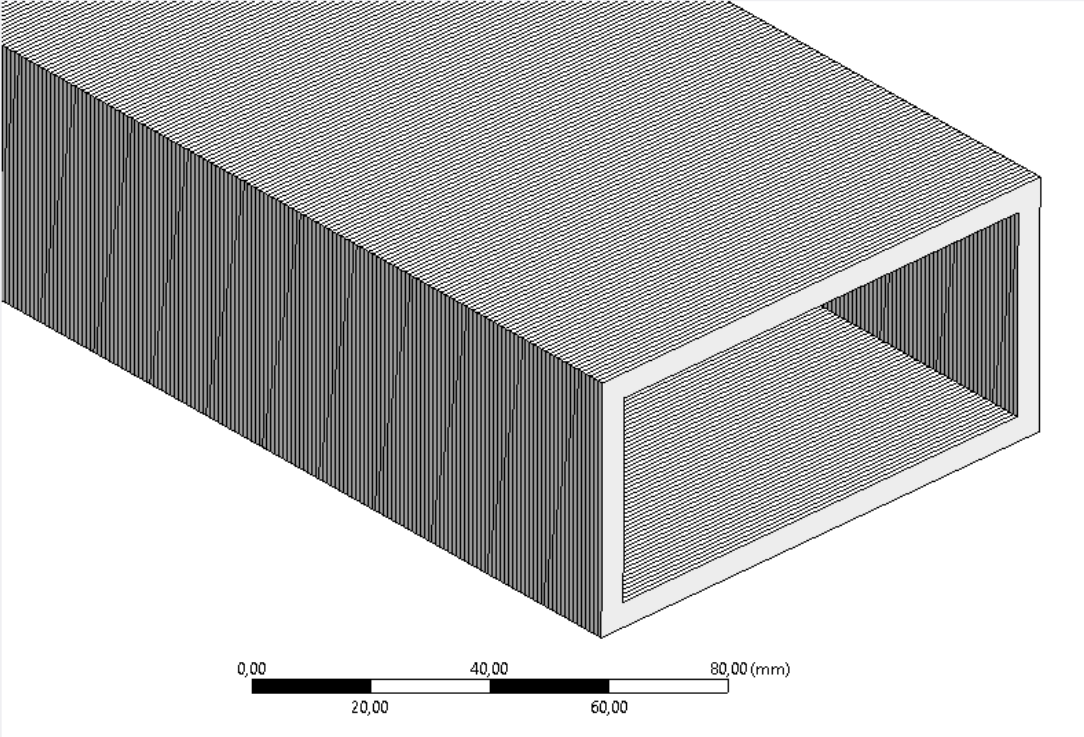
FE-model consists of LINE-type finite elements with a size equal to 1mm.
Solution Results
Datasets with the results of these solutions consist of three blocks:
- a = 50 mm, s = 5 mm;
- a = 100 mm, s = 10 mm;
- a = 200 mm, s = 20 mm.
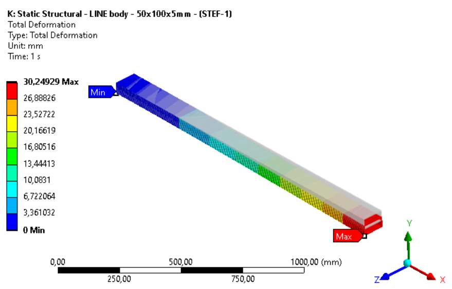
One of the examples of solution results is represented in the figure below. In this figure, we can see deformations of the beam with the next parameters: L = 1500mm, a = 50 mm, s = 5 mm, q = 0,575 N/mm.
Rectangular beam bending under static linear load
This repository contains the results of the FEM simulation of a simple rectangular beam bending. Two problems were analyzed:
1) Determination of the steel hollow beam rigidity in relation to its Width (B), Height (H), Thickness (s) and Length (L).
Problem statement: Line pressure acts on the cantilever beam, fixed on one side. Reactions in a place of fixation are equal for all solution cases. Results are presented in the file ‘Bend of rectangular hollow section beam.xlsx’;
2) Determination of the fiberglass hollow beam rigidity in relation to Length (L) and line pressure (q) magnitude for three types of beam sections: 50×100×5mm, 100×200×10mm and 200×400×20mm.
Problem statement: Line pressure acts on the cantilever beam. In this task maximal displacement of the beam is limited to 0,02L and the magnitude of the line pressure corresponds to the beam deformation of 0,02L. Results are presented in the file ‘Longeron (tube) - BENDING - Def=2%.xlsx’.
Solution results for these problems may be used to design various structures, e.g. a longeron of a wing.
Problem 1
Deformations of the steel beam with a rectangular section under line pressure were studied in this problem. Two methods were employed to find a solution. The first approach involved theoretical analysis using this equation:

where v – max deformation of the beam, m;
q – line pressure, N/m;
L – length of beam, m;
E – Young`s modulus, Pa;
J – beam section moment of inertia, m4.
The second approach is to apply the Finite Element Method using ANSYS Workbench software.
The solution was found for a linear deformation without accounting for the plasticity of the material.
Beam Dimensions
The scheme of the beam section is represented in the figure below.


Material Properties
The material of the beam is Structural Steel with the next characteristics:
E = 2*1011Pa;
µ = 0,3.
Boundary Conditions
The scheme of boundary conditions is represented on the figure below.

Where ‘q’ is a line pressure.
Gravity wasn’t taken into account.
Finite Element Model
FE-model consists of LINE-type finite elements with a size equal to 1mm.

Solution Results
Solution results of Problem 1 are represented for four cases:
1) ‘Variable Length’ – the length of the beam changes from 500 to 5000 mm while other dimensions are fixed (B = 10 mm, H = 10 mm, s = 1 mm, q = 0,1 N/mm);
2) ‘Variable Width’ – the width of the beam section changes from 5 to 100 mm while other dimensions are fixed (L = 1000 mm, H = 10 mm, s = 1 mm, q = 0,1 N/mm);
3) ‘Variable Height’ – the height of the beam section changes from 5 to 100 mm while other dimensions are fixed (L = 1000 mm, B = 10 mm, s = 1 mm, q = 0,1 N/mm);
4) ‘Variable Thickness’ – thickness of the beam section changes from 1 to 50 mm while other dimensions are fixed (L = 1000 mm, B = 101 mm, H = 101 mm, q = 0,1 N/mm).
One of the examples of the solution results is represented in the figure below. In this figure, we can see deformations of the beam with the next parameters: L = 1000 mm, B = 10 mm, H = 10 mm, s = 1 mm, q = 0,1 N/mm.

Problem 2
Deformations of the fiberglass beam with a rectangular section under line pressure were studied in this problem. Solutions were obtained with the help of the ANSYS Workbench software.
Deformations in ANSYS Workbench were found for the variable beam length, ranging from 1500 to 10000mm, and for three beam section dimensions:
- 50×100×5mm;
- 100×200×10mm;
- 200×400×20mm;
For each study a linear load was selected in such a way, that it should produce a tip deflection of 2% of the beam length based on the next equation:

where q – line pressure, N/m;
E – Young`s modulus, Pa;
J – beam section moment of inertia, m4;
v – max deformation of the beam, m;
L – length of beam, m.
The solution was found for a linear deformation without accounting for the plasticity of the material
The purpose of Problem 2 is to find relations between beam deformations and beam linear load magnitude with the condition that v=0,02L, and compare analytical and numerical results.
Beam Dimensions
The scheme of the beam section is represented in the figure below.


Material Properties
The material of the beam is Fiberglass STEF-1 with the next characteristics:
E = 2,16*1010Pa;
µ = 0,3.
Boundary Conditions
The scheme of boundary conditions is represented in the figure below.

Where ‘q’ is a line pressure.
Gravity wasn’t taken into account.
Finite Element Model
FE-model consists of LINE-type finite elements with a size equal to 1mm.

Solution Results
Datasets with the results of these solutions consist of three blocks:
- a = 50 mm, s = 5 mm;
- a = 100 mm, s = 10 mm;
- a = 200 mm, s = 20 mm.
One of the examples of solution results is represented in the figure below. In this figure, we can see deformations of the beam with the next parameters: L = 1500mm, a = 50 mm, s = 5 mm, q = 0,575 N/mm.

